When selecting the appropriate size of a linear actuator, applying one general number to make a selection, such as a maximum load rating, is difficult.
For instance, an application load of 25 lbs could be well under the max rating of the linear actuator but could also be inadequate if critical speed is exceeded. What happens to the actuator at higher loads? Does the linear actuator stop running entirely, or is there a significant reduction in life? Also, in some cases, the actuator is more capable than the stated load rating, and a safety factor is built-in. Due to the multiple components that make up the assembly and the intended application of the actuator, there are numerous aspects to consider. For example, the maximum design limit may be attributed to the load-carrying of the lead screw nut. In other cases, the gating item may be the radial bearing limitation for axial thrust, or the motor option selected is insufficient to drive the linear actuator at the rated load and speed.
Here are some considerations and logical steps to follow when sizing a linear actuator:
What questions should you answer when sizing a Linear Actuator?
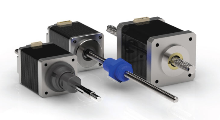
1 - Should the Linear Actuator Be Driven By a Lead Screw or Ball Screw?
Many actuators are built with lead screw or ball screw drive mechanisms. To determine which option is optimal for your application, you must consider load, speed, efficiency, back-drivability, cost, life, and repeatability requirements.
For higher loads and higher efficiency requirements, a ball screw is more often a better choice. For a given load requirement, it may be possible to use a smaller diameter ball screw than what would be needed if a lead screw were used.
CLICK HERE for more information on the differences between lead screws and ball screws.
2 - Repeatability vs. Accuracy
Accuracy
Accuracy in a linear actuator refers to point A to point B positional tolerance. For example, when the motor driver signals the actuator to move 1", accuracy is the actual distance moved versus the theoretical difference. If high accuracy is necessary, a precision rolled lead screw with .0003"/inch lead accuracy can be selected (accuracies as high as .0001"/inch are also available), or a precision-rolled ball screw is also suitable. In this case, the ball screw would generally be a class C7 (with some sizes available as high as grade C5). Because error from the precision rolling process is linear, it can be canceled out through changes in the firmware or by using linear/rotatory encoders to create a closed-loop system for continuous positioning feedback.
Repeatability
Repeatability measures how close or exact the linear actuator can return to a specific point from either direction of travel. The tolerance is highly dependent on the type of nut and lash (axial clearance) between the nut and lead screw or ball screw. Higher bi-directional repeatability requirements will benefit from a leadscrew with an anti-backlash nut. Multiple anti-backlash nut designs are available, like the axial, radial, and torsional nuts offered by Helix Linear Technologies. Besides providing zero backlash, these lead screw nuts are also compensating and will maintain their anti-backlash distinction through the life of the actuator.
Another optimal choice for high repeatability is a ball screw assembly with a selective fit ball nut to minimize the backlash. In this case, the balls are sized to the ball screw and loaded into the nut to achieve near-zero clearance conditions and meet application requirements. Backlash can be reduced to as little as .0002" (5 microns) when utilizing this method.
3 - To Backdrive or Not to Backdrive?
A ball screw typically has a 90% efficiency. The downside of this higher efficiency is back-driving. Backdriving results from the load pushing axial on the screw or nut to create rotary motion. A ball screw will require a brake to keep the system from back driving and maintain its position when the power is off.
If backdriving is a concern because the system needs to be self-locking during power outages, there is back pressure in the system, or static loading conditions exist, a lead screw is a better choice. Lead screws with less than 50% efficiency are self-locking, eliminating the higher cost of a brake needed to keep the shaft from turning. Space limitations may also prohibit a brake fitting into the design.
In some applications, it is necessary to backdrive the assembly. In this situation, a ball screw or a leadscrew assembly with an efficiency higher than 50% will provide this functionality.
4 - Does the Linear Actuator Need Lubrication?
The number one cause of bearing and ball screw failure is lubrication. Insufficient or poor application -- or simply using the wrong lubricant can lead to actuator failure. Outside influences impacting the lubrication, such as contamination, can also lead to degradation of the lubricant. Therefore, careful consideration should be given to the type of lubrication, including the thickening agent, viscosity, and purpose. Please consult with an Applications Engineer when making a lubrication selection. Multiple industry-specific options are available, including, Medical, Aerospace, and Semiconductor grades. When grease is not allowed or should be avoided, dry lubricants like PTFE and ceramic coatings can be applied to lead screw assemblies that utilize plastic nuts.
5 - What Safety Factor Should You Consider?
Most linear actuators have a safety factor built into the design load ratings. Typical safety factors are 1.5 to 2.0, but the required safety factor can be very application-specific.
- What is the maximum load?
- What is the maximum speed?
- Do the maximum load and speed co-occur, or will the linear actuator only see the higher loads at the slower speeds? (This is helpful to understand so that the linear actuator is not over-designed for conditions that will not happen simultaneously. )
- What is the duty cycle? (If it is very low or very high, this will influence the sizing and components used in the actuator.)
Designing for higher safety factors is easy, but doing so can substantially increase costs.
6 - Cost
All of the previously mentioned considerations directly correlate to the cost of a linear actuator. Review the requirements to determine which are essential for the application and successfully meet each axis's objectives. It may be worth customizing your actuator to get the features and benefits required so that you are not paying for something that is not needed, or worse, not getting what you need.
7 - Capacity
Is the linear actuator design load rating static or dynamic? If the load is dynamic, does that apply to all speeds? Maybe not. The Pressure-Velocity (PV) may be exceeded if it utilizes a plastic nut. In that case, a different nut material such as higher PV plastic, bronze nut, or ball nut may be required. Angular contact bearings can increase the axial thrust rating.
- Static Load- The maximum thrust load--including shock--that should be applied to a non-moving nut assembly.
(Note: The static load can be reduced through the selection of additional end machining options and screw mounting hardware.)
- Dynamic Load- The maximum recommended thrust load which should be applied to the lead screw and nut assembly while in motion.
8 - Stroke Length
Stroke length is often overlooked. Based on the unsupported length, the rotational speed of the lead screw or ball screw should not exceed the critical speed of the shaft. Critical speed is the rotational speed in RPMs that excites the natural frequency of the lead screw. Resonance will occur at the natural frequency regardless of the lead screw orientation (vertical vs. horizontal). Critical speed can be affected by both lead screw straightness and assembly alignment. The maximum recommended rotational speed is 80% of the calculated critical speed. Proper selection of end supports, diameter, and lead of the screw will improve the results.
9 - Operating Environment
When selecting the correct linear actuator for your application, the operating environment is a critical consideration. Harsh conditions, dust, and dirt will severely impact life and can cause the actuator to become inoperable. Linear actuators with a covered design or optional bellows will protect the guide systems or ball screw assembly. Sealed bearings should also be used in these cases. The lubrication of these components attracts debris from the environment. It is an excellent idea to protect the rolling elements, so they continue to move freely.
Wide temperature ranges or extreme cold temperatures can also impact the life and performance of the actuator. Materials that are compatible with the climate will ensure proper operations. High humidity applications can also create problems for the linear actuator. If these conditions exist, ensure the linear actuators selected are rated to withstand the elements.
10 - Is A Guide Rail Required?
Guide rails for linear actuators can take several forms. Rolling element linear bearings, traditionally called profile rails, are among the most common guidance systems used due to their load carrying capacity and ease of mounting. Rolling element linear bearings have two load capacity specifications, dynamic load capacity, and static load capacity.
Even after the load requirements are determined, attention should be given to what the orientation (horizontal, vertical, angled) of the linear actuator in the application will be. The loads can be on-axis of the guide system or offset to create a moment load condition. Determine whether the load is centered on the axis of the actuator or is it offset, creating a moment load (rotational forces) on the system. If the load is offset, what is the reaction force created? Pitch, Roll, and Yaw are three rotational forces about the X, Y, and Z axes. Each of these has its limits.
Consider how the linear actuator is being mounted. What may be a Roll rotational force on the carriage when the linear actuator is used horizontally can be Pitch if the linear actuator is used vertically. A Pitch force on the linear actuator used vertically may be a Yaw force if that same actuator mounting is turned 90 degrees.
If higher loads are needed, increasing the rail size, adding a second carriage block, using a longer carriage block, or changing the mounting orientation can all help keep the assembly from exceeding the maximum load limits. Consult with Helix Applications Engineers to determine the best linear actuator guide system and mounting for your application.
Conclusion
These are the steps and considerations for sizing and selecting linear actuators. Helix Linear provides a wide range of actuators customizable to fit a specific application or unique requirements. However, because there is no 'one size fits all' for linear actuators, we highly recommend working with a linear motion application engineer to discuss your requirements. (Book a meeting with our application engineers HERE). This partnership can help ensure that the linear actuator you select for your application turns into project success.


