
Understanding the Mechanics of Linear Actuators
A linear actuator is a motion device that moves something in a straight line instead of rotating it around a shaft. In practical terms, it turns electrical, hydraulic, or pneumatic energy into controlled push-and-pull movement for equipment such as adjustable furniture, robotics, sliding panels, valves, hatches, and industrial machinery.
This article explains how a linear actuator works, what parts are inside, which specifications matter, and how to choose one without creating avoidable performance or reliability problems.

How does a linear actuator work?
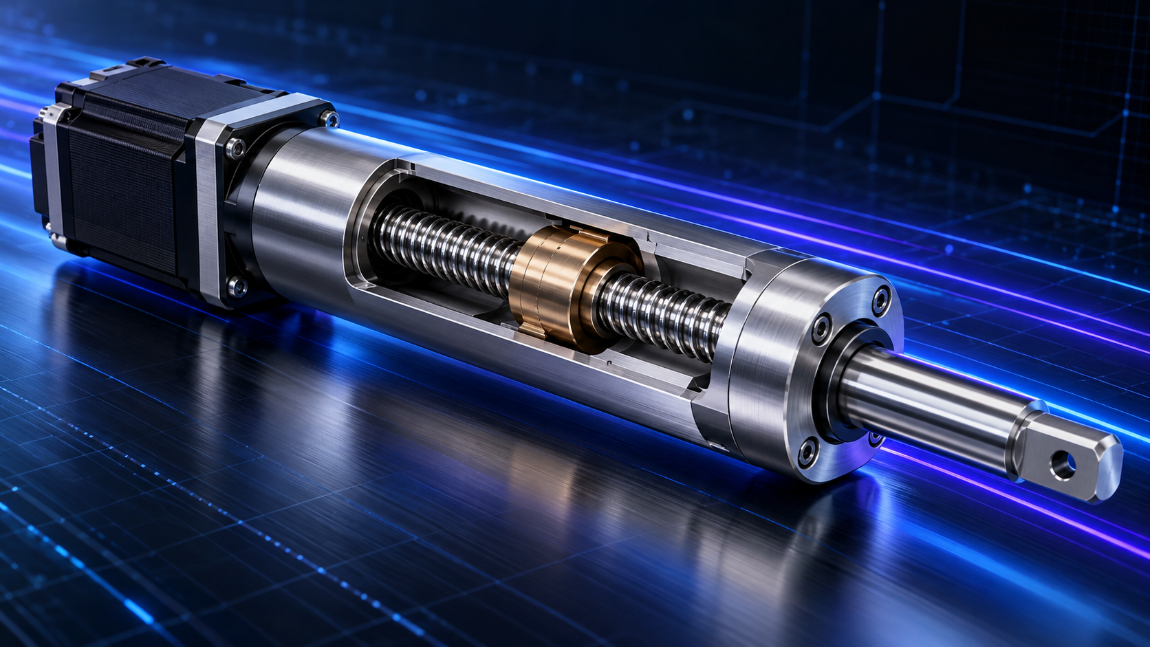
A linear actuator works by converting rotary motion into linear motion. In a typical electric unit, a motor spins, a gearbox adjusts that rotation for usable torque and speed, a lead screw turns, a drive nut travels along the screw, and an output rod extends or retracts to create straight-line movement. That mechanical chain is the heart of the linear actuator function and the reason a compact device can lift, slide, tilt, clamp, open, or position a load.
The simplest way to picture it is a powered screw-and-nut system. When the screw rotates, the nut cannot spin with it because it is constrained by the actuator housing. Instead, the nut moves along the screw, carrying the rod forward or backward. Reverse the motor direction, and the rod moves the opposite way.

This is why the phrase “what is a linear actuator and how does it work” often leads back to the same core idea: rotary input becomes controlled linear output. The exact design can vary, but the motion principle remains consistent across many electric actuators.
The main components inside an electric actuator
Most electric linear actuators look simple from the outside, but several parts work together inside the housing. Each one affects the actuator’s force, speed, precision, noise, duty cycle, and durability.
Motor
The motor provides rotational energy. Many compact electric actuators use DC motors because they are relatively easy to power and control, commonly in 12V or 24V systems. The motor’s size and design help determine how much work the actuator can perform, but the motor alone does not tell the full story.
Gearbox
The gearbox changes the motor’s output into a more useful combination of speed and torque. Lower gearing usually increases available force while reducing travel speed. Higher gearing can move the actuator faster but may reduce the load it can push or pull. This trade-off is central to actuator technology and explains why two actuators with similar dimensions may behave very differently.
Lead screw or ball screw
The screw is the part that converts rotation into linear travel. A lead screw is common because it is simple, durable, and can often hold position well when power is removed, depending on screw pitch and load conditions. A ball screw uses recirculating balls to reduce friction and improve efficiency, but it may be less self-locking and can require braking or additional holding support in some designs.
Drive nut and output rod
The drive nut rides along the screw and transfers motion to the output rod. The rod is the visible moving part that connects to the machine, bracket, lid, arm, gate, or linkage. Proper alignment matters here: the rod is designed primarily for axial push-pull loads, not bending or twisting forces.
Linear actuator types and where they fit
Different linear drive designs exist because not every motion problem has the same requirements. A small automation project, an outdoor hatch, and a heavy industrial lift may all need straight-line motion, but they do not need the same actuator.
Common types include:
- Standard rod actuators: General-purpose units for straightforward push-pull motion. They are often used where the load is aligned with the rod and side loading is minimal.
- Heavy-duty actuators: Built for higher force, rougher duty, or more demanding environments. These are common in industrial, agricultural, marine, or vehicle-related systems.
- Micro actuators: Compact devices for light loads and tight spaces, such as small robotics, electronics mechanisms, or lab equipment.
- Track actuators: Designs where motion is guided along a track rather than by an extending rod. They can be useful when the application introduces more side load or requires compact guided movement.
- Feedback actuators: Actuators with built-in position sensing, useful when the controller must know where the rod is, synchronize multiple actuators, or repeat positions accurately.
- Lifting columns: Telescoping actuator systems used for height adjustment, workstations, medical equipment, and ergonomic platforms.
- Dual-motion actuators: Specialized systems that combine linear movement with another motion, such as rotation, for more complex mechanical tasks.
Hydraulic and pneumatic actuators also produce linear motion. Hydraulics can generate very high force, while pneumatics can be fast and simple in facilities with compressed air. Electric linear actuators are often preferred when cleanliness, position control, lower maintenance, and easier integration with electronics are important.
Which specifications matter most?
The most important specifications are force, stroke, speed, duty cycle, feedback, voltage, mounting style, and environmental protection. Reading these values together is more useful than looking at one number in isolation. A strong actuator may be too slow, a fast one may overheat, and a correctly sized unit can still fail if it is exposed to the wrong environment or installed with poor alignment.
Force
Force describes how much the actuator can push or pull. Dynamic force refers to the force available while moving. Static force, sometimes called holding force, refers to the load it can hold when stopped. Do not size only for the average load; consider the worst-case position, friction, linkage geometry, startup loads, and a safety factor appropriate to the application.
Stroke length
Stroke is the full travel distance from fully retracted to fully extended. Choose enough stroke to complete the motion, but avoid excessive stroke if it creates packaging problems, slower cycle times, or unwanted mechanical leverage. Always verify that the actuator’s physical retracted and extended lengths fit the design.
Speed
Speed is usually measured as distance traveled per second or per minute, often under a stated load. Force and speed are closely linked. Through gearing and screw pitch, more force often means lower speed, while more speed can mean less available load capacity.
Duty cycle
Duty cycle describes how long the actuator can run compared with how long it must rest. Electric motors and gear systems generate heat, especially under load. If an actuator is used more frequently than its duty cycle allows, overheating and premature wear become likely.
IP rating and environment
The IP rating describes resistance to dust and water intrusion. Outdoor, washdown, marine, dusty, or dirty environments require more attention than clean indoor installations. Even then, an IP rating is not a promise that every chemical, impact, pressure wash, or temperature condition is acceptable.
A practical selection checklist
Choosing the right actuator begins with the job it must perform, not with the catalog photo. The actuator has to match the motion path, load, control method, mounting conditions, and environment.
Use this checklist before narrowing your options:
- Define the motion. Is the actuator lifting, sliding, tilting, clamping, opening, or positioning? Straight push-pull motion is easiest; linkages and pivots need more calculation.
- Calculate required force. Include load weight, friction, angle, leverage, acceleration, and the highest force point in the movement.
- Select the stroke. Confirm the needed travel distance and check both retracted and extended actuator lengths.
- Choose speed under load. Use loaded speed, not no-load speed, when estimating cycle time.
- Verify voltage and power supply. An undersized supply can cause slow movement, voltage drop, stalling, or unreliable control.
- Check duty cycle. Match the actuator to how often it will actually run, including repeated cycles during setup or peak use.
- Match the environment. Consider water, dust, temperature, vibration, shock, and corrosion exposure.
- Decide whether feedback is needed. Position sensing matters for automation, repeatability, and multi-actuator synchronization.
- Plan the mounts. Use brackets and pivots that keep the load aligned and allow natural movement through the full stroke.

How feedback changes control
Feedback allows a controller to know actuator position instead of simply powering the motor for a guessed amount of time. This becomes important when you need repeatable positions, synchronized movement, automated presets, or closed-loop control.
Common feedback methods include potentiometers, Hall effect sensors, and encoders. A potentiometer provides an analog position signal. Hall sensors count pulses from motor or shaft movement. Encoders can support more precise position tracking, depending on the design and controller. The best option depends on the required accuracy, electrical interface, environment, and control complexity.
Without feedback, two actuators of the same model may not move in perfect synchronization under different loads. For a single hatch or simple slide, that may not matter. For a platform lifted by multiple actuators, it can matter a great deal.
Installation details that protect performance
Many actuator problems are not caused by the actuator itself. They come from side loading, weak brackets, misalignment, poor wiring, or unrealistic assumptions about the load.
Side loading is one of the most common issues. A rod actuator should push or pull along its axis. If the mechanism bends the rod sideways, the screw, nut, bushings, and seals can wear quickly or bind. Use clevis brackets, pivot mounts, guides, rails, or linkages that let the actuator move naturally as the geometry changes.
Self-locking also deserves attention. Some lead screw actuators can hold position without continuous power, but this depends on screw design, load, vibration, and orientation. If movement after power-off would create a safety risk, use a design with verified holding capability, braking, mechanical locks, or another safety measure rather than assuming the actuator will hold.
Common mistakes to avoid
The same sizing errors appear across many
- Ignoring peak force: A hinged lid may need far more force near the start of travel than near the end.
- Confusing static and dynamic ratings: Holding a load and moving a load are different requirements.
- Forgetting side loads: The actuator may be strong in compression but vulnerable to bending loads.
- Undersizing the power supply: The system must deliver enough current at the required voltage under load.
- Overrunning duty cycle: Repeated movement can overheat the motor even if each motion is brief.
- Using the wrong environmental protection: Indoor-rated components may fail quickly outdoors or in wet areas.
- Expecting open-loop synchronization: Multiple actuators usually need feedback or mechanical coupling if they must move together evenly.
A simple example of matching actuator to task
Imagine a designer automating a small access panel. The panel swings on hinges, needs to open 12 inches at the actuator connection point, and must move slowly enough to avoid slamming. The designer starts by calculating force at the most difficult part of the swing, not just the panel’s weight. Then they choose a stroke that reaches the required open position, check that the actuator fits when retracted, and select a speed that gives a controlled opening time.
If the panel is outdoors, the designer also checks the IP rating, temperature range, bracket corrosion resistance, and water exposure. If the panel must stop at preset positions, feedback becomes useful. If it only opens and closes fully, limit switches and a simpler control setup may be enough.
Industries and applications for linear actuators
Linear actuators support equipment that needs controlled lifting, positioning, pushing, or pulling. Although the basic motion principle stays the same, each industry introduces different requirements for precision, force, operating life, and environmental protection.
-
Factory automation and robotics: Linear actuators position parts, adjust fixtures, operate clamps, and move tooling. Selection depends on cycle speed, repeatability, load, and integration with machine controls.
-
Medical and life sciences: Applications include laboratory sample handling, diagnostic equipment, fluid dispensing, and adjustable medical equipment. Compact size, smooth movement, cleanliness, and precise positioning can be especially important.
-
Aerospace and defense: Actuators can position mechanisms, adjust equipment, and operate access panels. These applications may require careful evaluation of weight, vibration, temperature extremes, reliability, and traceability.
-
Semiconductor and electronics manufacturing: Linear motion supports inspection systems, component placement, dispensing, and equipment adjustments. Designs may need low particle generation, controlled acceleration, and consistent positioning.
-
Packaging and material handling: Actuators adjust guides, position stops, divert products, and support machine changeovers. Stroke, throughput, duty cycle, and synchronization help determine the right configuration.
-
Agriculture and off-highway equipment: Linear actuators adjust gates, vents, implements, and dispensing mechanisms. Dust, moisture, shock, corrosion, and changing outdoor temperatures influence selection.
A complete actuator combines several motion components into a working assembly. Helix Linear Technologies supplies linear motion components and actuator solutions that engineers can evaluate against their application’s load, travel, speed, accuracy, and operating conditions.

How Helix actuators fit
We offer stepper motor linear actuators in three designs to match different machine layouts:
-
Captive actuators include built-in anti-rotation, creating a compact assembly for controlled push-and-pull motion.
-
Non-captive actuators move the lead screw through the motor and rely on the surrounding equipment to prevent screw rotation.
-
External actuators use a rotating lead screw to move an externally guided nut and attached load.
Helix’s stepper actuator portfolio includes NEMA 8, 11, 14, 17, 23, and 34 frame sizes, with availability depending on the design and configuration. For specific travel examples, the SMA-C-250024-0.5 offers a 0.5-inch (12.7 mm) stroke with NEMA 14 or 17 motor options, while the SMA-C-375062-01 provides a 1-inch (25.4 mm) stroke with a NEMA 23 motor.
These options let you match the actuator’s layout, travel, and motor size to the application. Helix application engineers can help you evaluate the required load, speed, duty cycle, and guidance before selecting a configuration.
The key takeaway
Understanding how a linear actuator works makes selection much easier. The motor, gearbox, screw, nut, and rod work together to turn rotational energy into dependable straight-line movement, but the right choice depends on the full system around the actuator. When you evaluate force, stroke, speed, duty cycle, environment, feedback, and mounting as connected decisions, you are far more likely to get a linear drive that performs reliably in the real application, not just on paper.
If you have further questions about linear actuators, please reach out to our application engineers here at Helix. We're happy to help!
